How to set up the experiment (step by step)
CONDITION THE ELECTRON GUN (30 mins)
Ignore any instructions to flick switches on the front
Conditioning filament current -> voltage reading on multimeter set to 146 mV
Leave at 146 mV for running, switch to operating mode
PURGE THE GAS LINE (10 mins)
Can be done during conditioning
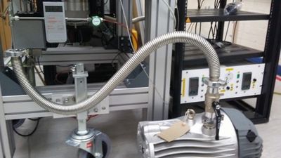
- open up the Argon gas bottle (outside the lab) ensure that there is pressure both in the bottle & in the line.
- follow instructions on the wall to purge the line
Assuming you have already opened up the gas bottle outside.
1. Close the green valve (Red arrow above). The Open/Close directions are marked on the valve
2. Start the scroll pump and open the ball valve above the scroll pump (when the black handle of the ball valve is vertical it’s fully open).
3. You should be able to monitor the pumpdown of the gas line on the battery operated pressure gauge. The pressure should reach 6e-2mbar after approx. 3 mins.
4. Once the pressure reaches approx. 6e-2mbar, close the valve above the scroll pump (handle should now be horizontal) and open the green valve. This will fill the gas line with helium up to approx. 1000mbar (you should be able to monitor the increase in pressure on the battery gauge).
5. Then close the green valve and repeat the above steps at least 3 times before starting the experiment.
At present, we CLOSE the green valve and CLOSE the gas bottle during the experiment, using the Argon in the line. (DO NOT fully open the VAT valve during operations - particularly if you operate with the gas bottle open - the Argon could completely fill the vacuum vessel. Fail.)
NB. Base pressure on the vacuum gauge should be 1.4-1.5E-10 mbar.
SWITCH ON EQUIPMENT ON RACKS
- Oscilloscopes
- WF generators
- 4 x WMA300 amplifiers
- DC voltage supply (set to 25V DC output to MCP end caps)
- signal amplifier
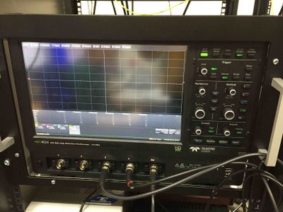
Scope 1 setup:
- Ch1: 0
- Ch2: 0
- Ch3: e-gun FCUP (not used in labview)
- Ch4: Faraday cup readout from signal amplifier
- Ext: 3rd Trigger (in labview) which comes from USER2 on the NI timing block – triggers the ramp. Cable is labelled USER2.
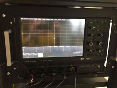
Scope 2 setup:
- Ch1 – 4: Probes on CROD1/3, CROD 2/4, FC 2/4, FC1/3. Colours correspond to probes.
- Ext: Same as Scope1. 3rd Trigger (in labview) which comes from USER2 on the NI timing block – triggers the ramp. Cable is labelled USER2.
CREATING WAVEFORMS
> C:/IBEXexp/code/waveform_create
Files to look at: WavefunctionCreator_perturbation.py
Calls the modules in Functions_perturbation.py and splices everything together in the correct format. Gives option as to whether you want to wait before perturbation, whether to apply a perturbation and whether to interleave measurements without a perturbation. Commented in the script in detail.
- Accumulation tune: 0.15 (previously used 0.114) - Tune to start scan at initial_tune and end at final_tune and number of tune points. - If no perturbation, segment_length [default 100] doesn’t matter. Default of 100 should be OK for perturbations up to 500 rf periods. If you want to use a longer perturbation, this needs to be adjusted (discuss with Lucy). - Rods_powered 2 or 4 (4 default) - Perturbation (is the bit you might have to change). Asks for details of perturbation, which (if no perturbation just set amplitude to zero) asks for frequency, amplitude, no. of rf periods to keep it on for (this must match the setup in the Labview, see later step), and then with/without the alternate measurements with the perturbation off, and with/without a wait time (default 0 wait time). - Ramp_time default 100 E-6 (100 microseconds or rf periods) - Voltage_offset: DC offset on the main rods, default 10V - Endcap_offset: DC offset on endcaps, default 25V (NB. Check this matches the DC power supply) - Amplifier gains (calibrated) do not change without additional calibration
Set up as per your requirements.
> RUN-> RUN MODULE (click OK to save it)
- Takes a while to run (5 minutes), check it doesn’t crash. - If running with perturbation with alternate measurements, first run with 0V perturbation strength, then run again with the amplitude of the perturbation (script will save waveforms with different filename). - Put files in waveform_create folder. Default on LabView is to take files from that folder.
Functions_perturbation.py Has a bunch of modules/functions for making sinusoidal patterns: - Quadrupole perturbation (or without). Dipole perturbations are possible with a different setup/wiring of the feedthroughs/rods. - Main confinement waveform - Ramps
SETTING UP LABVIEW
NB. The Labview when in Automated mode steps through filenumbers that you give in the previous step. So you need to set those up first.
> IBEX All-inOne V2.vi
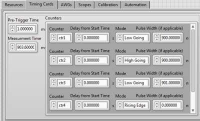
Timing Cards tab
(cannot reset defaults) set these values:
- Pre-trigger time: 1 msec
- Measurement time: 903.6 msec
- Adjust Timing Cards:
- Ctr1: Low Going, 900 msec -> either G2 or G4 on the gun (TBC)
- Ctr2: High going, 900 msec -> either G2 or G4 on the gun (TBC)
- Ctr3: Low going, 901 msec -> triggers ramp
- Ctr4: (NOT USED)
This gives the following timing pattern: Egun (ON 0-> 900 msec), (OFF 900 -> 903.6 msec) Rods off (0 -> 700msec), ON at trapping voltage (700 -> 901 msec), RAMP (901->901.1 msec), STORE (to 901.6), EXTRACT -> (901.6 - 903.6 msec)
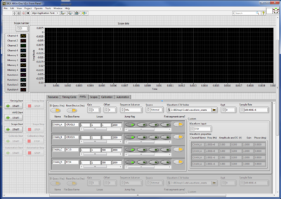
AWGs tab
Sample rate: 100E+6
CROD13,CROD24 rows: 1=‘accumulate’, 1= ‘ramp’, 1=’store at new voltage and use the segment created by waveform_create (which has 500 periods), 2000 = number of rf periods during extraction, needs to be long enough to extract.
NB. To reset the AWGs to 0 amplitude at the end of the experiment (current configuration), add an additional segment to the timing setup, by entering a number in the 5th column and click the greyed out button twice to create an ‘off’ light button (i.e. jump flag off = automatically proceed). Repeat for all 4 rows. At present the waveform files that this uses are created manually with the next segment number using functions_perturbation.py.
FC13,FC24 rows: 3rd entry = 500 (as the waveform for this only has 1 rf period).
Jump flags should be ON for the start & none of the rest
Scopes tab
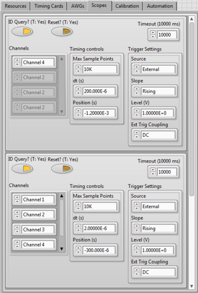
Trigger for scopes. Trigger settings should both be External, Rising Edge and 1.0V. Timing controls sets the timebase and any offset. Will need to adjust these if the ramp time (for example) changes to center the signal pulse on the scope. Check screenshot for Lucy’s values for setup used in this example.
PUT GAS IN
- Open CPA software from VAT
- Set pressure actual pressure voltage to 6.6 and press enter.
VAT valve will set (pressure will increase) and check pressure gauge now at around 2.7E-7 mbar. DO NOT HIT FULLY OPEN ON VAT!!
BEFORE RUNNING: SANITY CHECK
The Labview is programmed to repeatedly run just the first file for you to check that everything is working properly before you hit <Automation Start>. To make it run this check:
- Hit Run on LabView (top left)
- Timing start
- AWG start
- Scope start
- Check in ‘Resources tab’ that nothing is RED.
- Scope display will change a bit and display a plasma signal. Whoop!
- If you want to adjust the position of the signal on the scope, hit <Scope Stop> and then in the Scope tab, change the position, hit <Scope Start> again to check the outcome.
- Check Scope 2 waveform signals to make sure the amplitude is both within the scope and what you expect it to be. Change on physical scope if not. Compare amplitudes to tune chart on the wall to make sure it’s what you expect for your first tune value. The blue/green traces should be higher than the red/yellow as the end caps have an extra DC voltage in the STORE period.
- When you’ve fnished the sanity check, hit <SCOPE STOP> and <TIMING STOP> then <STOP> the LabView.
WHEN YOU’RE READY TO ROLL
- Automation Tab > open Results path > Create a Folder for today
- Baseline > First Experiment (runs one with the egun OFF so no ions to baseline the signal)
- First File: 0, Last File: 199 (if you ran 200 points), Samples per file: 2 (for now)
- START Labview
- Press Scope Start + Automation Start (soon after each other)
While it’s starting to run, check automation & resources tab in case of any errors
- Check the Results Folder that you created is populated with results (with a real file size)
Much of the time it displays fairly strange signals as the AWGs reset, don’t be alarmed. It should periodically show you a proper plasma signal. On the Automation tab, it will count through the files that it’s running. Watch it for roughly the first 10 and by that time the estimated finish time should be fairly accurate (it will come down from the initial value).
Things to check for during running
Check that the ion signal fits and isn't clipped! If it is, you need to STOP and change the setup or your results will be useless.
IF YOU NEED TO STOP
- Automation STOP
- Scope STOP
- STOP LabView
WHEN IT’S FINISHED
- It should stop the automation process, but you need to hit STOP on the LabView. You can now close the LabView.
- Copy the results over to \\ISISShares\Accelerator_R&D\IB_Group\IBEX\Data\2018\Month\
- Then you can access your results (as long as you can VPN in) from your own computer.
SHUT DOWN PROCEDURE
- Close VAT valve
- Switch off Amplifiers
- Switch off AWGs
- Switch off DC power supply
- Switch off oscilloscopes
